In this article:
Overview - Basic overview of Sensor system
Sensor Types - Introduction to the sensor factories
Creating a Sensor - How to create a new Sensor
Creating a PowerShell Sensor - How to author a new PowerShell Sensor
Creating a VBScript Sensor - How to author a new VBScript Sensor
Creating a WMI Sensor - How to author a new WMI Sensor
Creating a Workflow Sensor - How to author a new Workflow Sensor
Saving and Deploying a Sensor - How to save a new Sensor
Further Information - Where to go for further information
Overview
Adaptiva Sensors are objects that can be deployed to endpoints to retrieve data.
They are primarily used by the Endpoint Inventory product to retrieve data for inventory purposes.
Sensors can take many forms and perform differently, depending on the type of sensor that has been authored.
Sensors can be accessed from the left-hand menu in the web UI, under the Endpoint Inventory product.
Sensor Types
- Java - These sensors are built-in and cannot be authored manually. They perform activities that interact directly with the Adaptiva Client on the device.
- PowerShell - These sensors will run a specified PowerShell script on the device and output data using return parameters that are specified within the script itself.
- VBScript - These sensors will execute a specified Visual Basic Script (vbs) on the device and output data using WScript.Echo commands specified within the script itself.
- WMI - These sensors allow you to specify either a WMI query or class to pull data from. The specified query or class will be interrogated from the Windows Management Instrumentation on the device and the respective rows will be returned.
- Workflow - These sensors allow you to specify an Adaptiva Workflow to execute to return data. The Sensor system will leverage the ResultArrayOfRows property on the End node of the workflow to collect data. Workflows used as Sensors must add any return data as Row objects to the ResultArrayOfRows property. To do this, workflows must use the RowOperations workflow activity.
Creating a Sensor
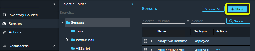
To author a new sensor from the Sensors browser, select +New in the top-right corner
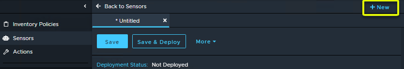
To author a new sensor from within the Sensor editor, select +New in the top-right corner
This will open a new editor window where you can select a type of sensor to author.
Give the Sensor a Name, optionally add a Description, select the Sensor Type from the drop-down list and choose whether the sensor produces Volatile data.
Volatile Data: Select this option if the sensor data is subject to frequent change (i.e. processes running, or system uptime etc.). For most sensors that return data that doesn't change very often (i.e. hardware information, BIOS version etc.) this flag should be set to False.
Creating a PowerShell Sensor
First, create a new Sensor by following the Creating a Sensor section. Select PowerShell as the Sensor type.
PowerShell Sensors return properties of objects. These objects can either be a native PowerShell object, or a custom object. We will use the same example for both.
For this example, we will create a PowerShell Sensor that returns the current version of PowerShell that's installed on the device.
Returning using a built-in object
The command to retrieve the version details of PowerShell is $PSVersionTable. This built-in object has several properties which we can see when we run this in PowerShell:
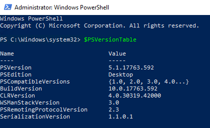
One of the properties is PSVersion which contains 4 sub properties; Major, Minor, Build, Revision:
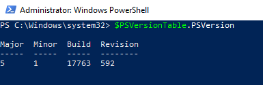
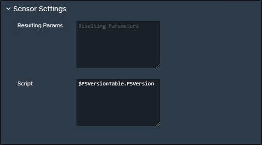
To output these properties, we can simply enter $PSVersionTable.PSVersion as the script:
Returning using a custom object
Alternatively, we can return a custom object. This is useful when we want to perform manipulation or output a primitive value such as a custom string.
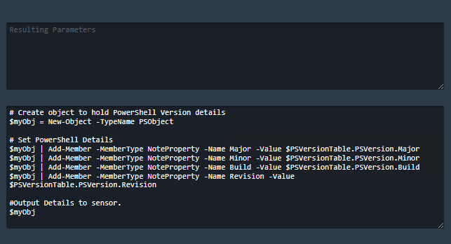
We can rewrite the script in the following way:
# Create object to hold PowerShell Version details
$myObj = New-Object -TypeName PSObject

# Set PowerShell Details
$myObj | Add-Member -MemberType NoteProperty -Name Major -Value $PSVersionTable.PSVersion.Major
$myObj | Add-Member -MemberType NoteProperty -Name Minor -Value $PSVersionTable.PSVersion.Minor
$myObj | Add-Member -MemberType NoteProperty -Name Build -Value $PSVersionTable.PSVersion.Build
$myObj | Add-Member -MemberType NoteProperty -Name Revision -Value $PSVersionTable.PSVersion.Revision

#Output Details to sensor.
$myObj
In this example, we are first creating a new object called $myObj. We are then adding four properties to $myObj called Major, Minor, Build and Revision and assigning them to the Major, Minor, Build and Revision properties of the $PSVersionTable.PSVersion property. Finally, we are outputting the details of the sensor by returning the $myObj.
The final script looks like this:
Adding Input Properties
We have the option to add Input Properties to the script using the Sensor Input Parameters section of the editor. Adding an input property here will add a block of script to the Resulting Params section of the Sensor Settings script section.
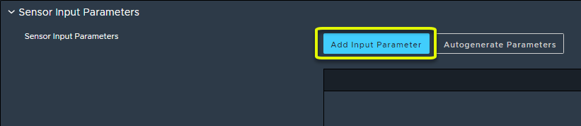
To add an Input parameter click the Add Input Parameter button.
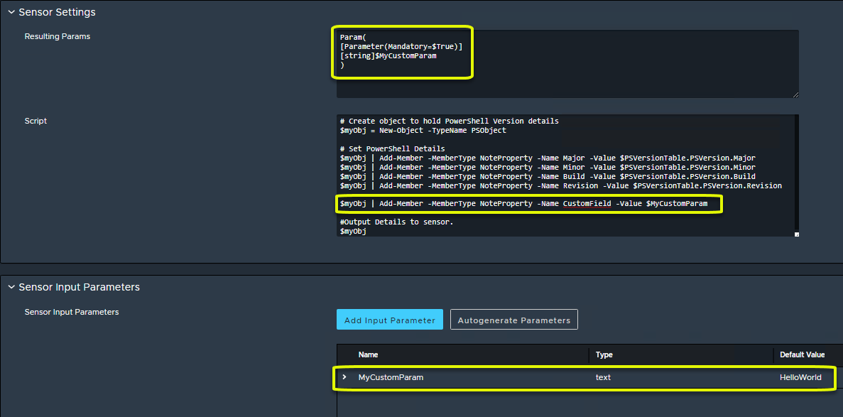
Give the parameter a Name, optionally enter a Description, choose whether this parameter is Required (i.e. it has to be specified for successful execution), the data type of the parameter and optionally a Default Value. Then click OK.
The appropriate parameter will get added to the Resulting Params section and you can now use that parameter within your script, for example:
Adding Output Schema
The final thing to do is to add output schema.
Important: the output schema must match exactly with the output properties in the script.
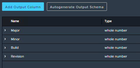
For this example, the script outputs four properties; Major, Minor, Build, Revision. Therefore we will add four Output Columns with these exact names
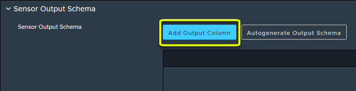
To add an output column, select Add Output Column.
Ensure the schema Name value matches exactly with the script property to return, optionally give a Description, and select a Type which matches the type being returned by the script. In the case of example, all four values are numeric so we will select Whole Number.
The only thing left to do is save and deploy the sensor. Please refer to the Saving and Deploying a Sensor section.
Creating a VBScript Sensor
First, create a new Sensor by following the Creating a Sensor section. Select VB Script as the Sensor type.
For VBScript Sensors, return values are determined by what gets output by the script.
In order to return data, the script must return values using WScript.Echo.
Every line returned constitutes a new row. For multiple columns, output should be separated by comma (,). To include a comma in the output of a single row, the escape character tilde (~) can be used before the comma.
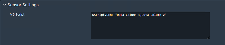
In the Sensor Settings, enter the VBScript used to collect data. For this example we will simply output a fixed text string with 2 columns:
WScript.Echo "Data Column 1,Data Column 2"
Adding Output Schema
The final thing to do is to add output schema.
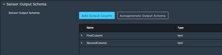
Important: the output schema column count must match the output returned by the VBScript. In the case of the above example, the script returns two columns, so we must add two output columns. The column names can be anything and should represent the data being returned. The order of the columns should be the same order that the data is output by the VBScript.
To add an output column, select Add Output Column.
Give the column a Name, an optional Description and select the data type that is being returned. In this case both columns will be text strings so we will select Text.
The only thing left to do is save and deploy the sensor. Please refer to the Saving and Deploying a Sensor section.
Creating a WMI Sensor
First, create a new Sensor by following the Creating a Sensor section. Select WMI as the Sensor type.
When authoring a new WMI sensor there are two options available; Query or Class
In this example we will use the same example for both - we wish to query BIOS information from the clients.
Creating a new Query WMI sensor
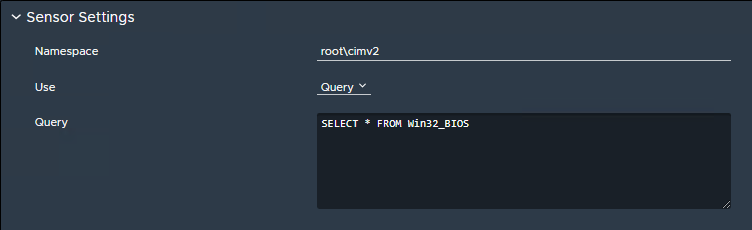
Within the Sensor Settings section, enter a WMI namespace (e.g. root\cimv2) and choose the Query option.
Enter your desired WMI query. In this example we will enter the following:
SELECT * FROM Win32_BIOS
Creating a new Class WMI sensor
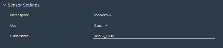
Within the Sensor Settings section, enter a WMI namespace (e.g. root\cimv2) and choose the Class option.
Enter your desired WMI class name. In this example we will enter Win32_BIOS.
Adding Output Schema
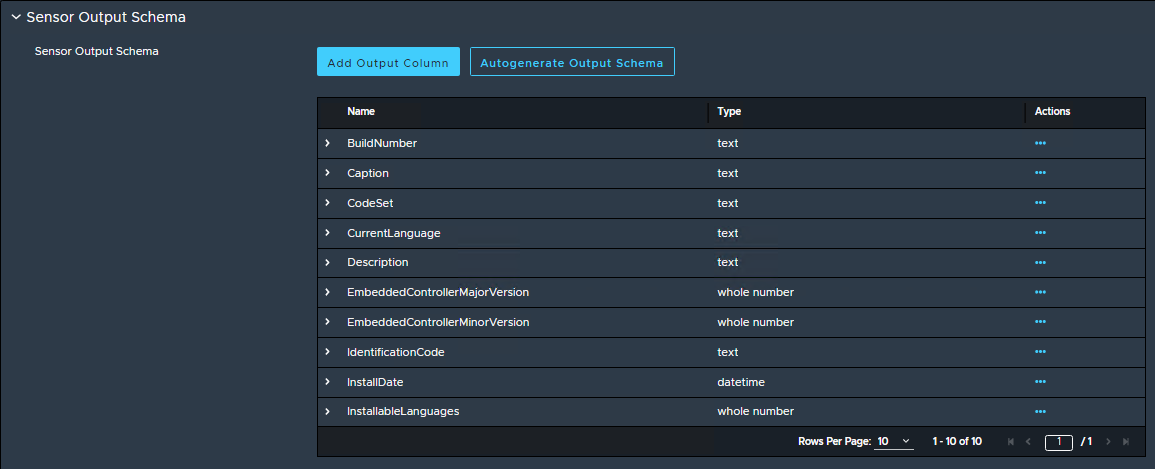
If the WMI namespace and class/query is available on the Adaptiva Server, the easiest way to generate output schema is to click Autogenerate Output Schema.
This will allow you to select the properties from the class/query and will automatically add the selected properties as output schema columns.
Alternatively, or if the class/query is unavailable on the Adaptiva Server, the output schema must be added manually. For each output property to return, click the Add Output Column button and add a new output property. To add an output column, select Add Output Column.
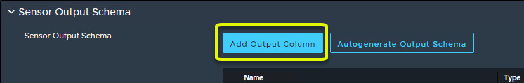
Ensure the schema Name value matches exactly with the WMI properties to return, optionally give a Description, and select a Type which matches the WMI type being returned.
The only thing left to do is save and deploy the sensor. Please refer to the Saving and Deploying a Sensor section.
Creating a Workflow Sensor
Authoring the Workflow
The Sensor system will leverage the ResultArrayOfRows property on the End node of the workflow to collect data. Workflows used as Sensors must add any return data as Row objects to the ResultArrayOfRows property. To do this, workflows must use the RowOperations workflow activity.
For this example we are going to author a new workflow that will output basic IP information about a client.
First we will create a new client workflow. For more information on creating workflows, please see this article. We will give the workflow the name Sensor - IP Info.
We will then add an IPAddressInfo activity. This will retrieve the IP address information for the machine for the primary NIC that it is using to communicate with the Adaptiva Server. This activity returns a lot of different output properties. For this example we will just use IpAddress and IpSubnetMask.
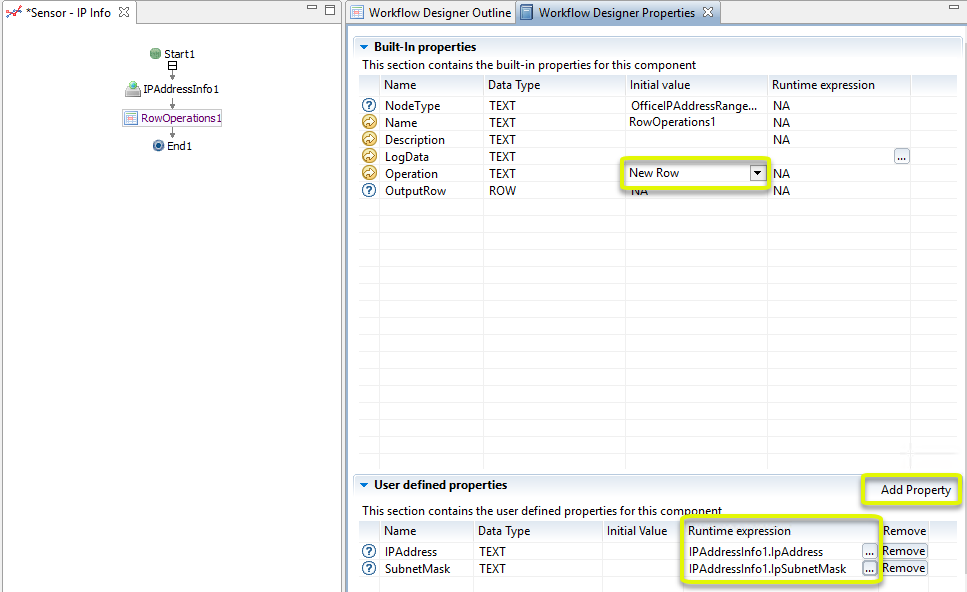
Next add a RowOperations workflow activity.
Ensure the Operation is set to New Row.
We are now going to assign User Defined Properties for every property that we wish to return.
Here we will add two user defined properties; IPAddress and SubnetMask and assign them to IPAddressInfo1.IpAddress and IPAddressInfo1.IpSubnetMask respectively:
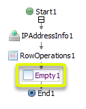
We will then add an Empty activity to assign this row to the ResultArrayOfRows property on the End1 node
Step 1: Add a new Empty workflow activity
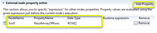
Step 2: In the External Node Property Setter in the bottom right of the window, add a new Property and select End1 as the Node Name and ResultArrayOfRows as the Property Name:
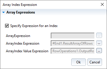
Step 3: In the Runtime expression section, click the ellipse button (...) to bring up the Array Index Expression dialog box. Tick the box to Specify Expression for an Index and then click the ellipse button (...) next to ArrayIndexExpression. Enter the following text:
#End1.ResultArrayOfRows
Click OK and then click the ellipse button (...) next to ArrayIndex Value Expression. Enter the following text:
RowOperations1.OutputRow
Click OK and you should have the following:
Click OK to commit. This will assign the row to the next available index within the ResultArrayOfRows property. In this case, as there is only one result returned, it will be Index 0.
For workflows that should output multiple rows, simply place the RowOperations1 and Empty1 statements inside of a While loop.
Right-click anywhere in white space on the workflow designer canvas and click Save and Deploy. Optionally enable logging and click OK. The workflow can now be used as a sensor.
Creating the Sensor
First, create a new Sensor by following the Creating a Sensor section. Select Workflow as the Sensor type.
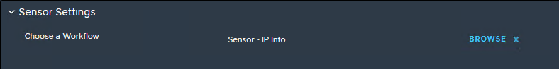
In the Sensor Settings section, choose your Sensor workflow. In this case we will select the Sensor - IP Info workflow.
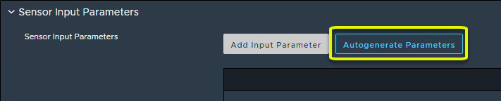
Adding Input Properties
If the workflow you have selected has any user defined properties on the Start node, these can be assigned to the Sensor by selecting Autogenerate Parameters.
Adding Output Schema
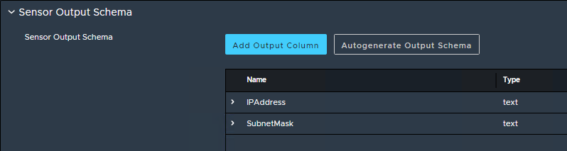
The final thing to do is to add output schema.
Important: the output schema must match exactly with the output properties in the row returned by the workflow.
For this example, the workflow outputs a row with two properties; IPAddress and SubnetMask. Therefore we will add two Output Columns with these exact names
To add an output column, select Add Output Column.
Ensure the schema Name value matches exactly with the row property to return, optionally give a Description, and select a Type which matches the type being returned by the row property. In the case of example, both values are textual so we will select Text.
The only thing left to do is save and deploy the sensor. Please refer to the Saving and Deploying a Sensor section.
Saving and Deploying a Sensor
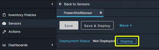
To save and deploy the sensor we can use the buttons at the top of the page. Save will save the metadata about the sensor, but not make it available for use. Save & Deploy will save and make it available for use within policies. Note: Deploy will NOT send to any clients.
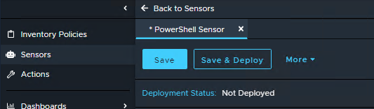
Note: After clicking Save instead of Save & Deploy, the Save & Deploy button will be greyed out and in order to make the sensor available to assign to clients, the Deploy button next to Deployment Status must be used instead:
Further Information
For further information, please see the other resources in the Technical Reference Library or speak to a member of Adaptiva Support.
If you experience any issues or suspect there is a bug in any part of the sensor system, please log a support ticket and a member of the Adaptiva support team will be touch as soon as possible.
Comments
0 comments
Article is closed for comments.